Technical Guides

Choosing a VSD for Commercial HVAC and Cooling Towers
What to look for in a VSD for air handling units, cooling towers and chilled-water pumps: humidity and IP rating, harmonics, BMS protocols and cooling tower…
Read moreHow the Himel HDM3 moulded case circuit breaker works, what breaking capacity means, and how to size and set it correctly for Singapore panels.
4 July 2026 · 9 min read · Trans-Digi Global
The Himel HDM3 is a moulded case circuit breaker (MCCB): a switching and protection device that carries normal load current and opens automatically on overload or short circuit. To size it, you choose three things in order: a rated current (In) at or just above the circuit’s design current, a breaking capacity (Icu) at least equal to the prospective fault current at the board, and the right pole and trip-unit configuration for the load. This guide walks through each step using the figures in Himel’s HDM3 catalogue.
In this article
Trans-Digi Global is an authorised Himel partner in Singapore and supplies the HDM2 and HDM3 MCCB range from local stock, with the datasheets and as-built documentation that panel submissions need.
An MCCB protects the cable and equipment downstream of it against two different faults:
Himel describes the HDM3 as its 3 Series range of MCCBs with a fixed thermal-magnetic trip unit, providing line protection and motor protection up to 1,600 A. Two related families sit alongside it: the HDM3E with an electronic trip unit (LSI protection), and the HDM3L earth-leakage MCCB up to 630 A (Himel HDM3 catalogue).
Because the HDM3 trip unit is fixed, you select the breaker rating to suit the circuit rather than dialling a setting on site. That matters when you compare quotations: two breakers with the same frame size but different In values are not interchangeable.
Compared with a miniature circuit breaker (MCB) such as the Himel HDB9, an MCCB covers higher currents and higher fault levels. MCBs are tested to IEC 60898-1, which covers devices up to 125 A and 25 kA short-circuit capacity, while MCCBs are tested to IEC 60947-2, the standard for industrial circuit-breakers up to 1,000 V AC.
The short answer: use an MCB for final circuits, up to 125 A at most, where the prospective fault current at the board is within the MCB’s breaking capacity. Use an MCCB when the current or the fault level is higher, or when the circuit needs a motor-protection or adjustable trip unit. Whichever you choose, the same two rules apply: the design current must not exceed the rating, which must not exceed the cable rating (Ib ≤ In ≤ Iz), and the breaking capacity must be at least the prospective fault current.
| MCB (e.g. Himel HDB9, HDB3w) | MCCB (e.g. Himel HDM3) | |
|---|---|---|
| Product standard | IEC 60898-1, for household and similar installations; some industrial MCBs are tested to IEC 60947-2 | IEC 60947-2, industrial circuit-breakers up to 1,000 V AC |
| Current range | IEC 60898-1 covers up to 125 A. HDB9: 1–63 A; HDB3w-125: 63–125 A | HDM3 frames from 100 A to 800 A (In 10–800 A); the HDM3 range extends to 1,600 A |
| Breaking capacity | IEC 60898-1 covers up to 25 kA. HDB9: 6 or 10 kA | HDM3 Icu 25–70 kA at 400/415 V, depending on frame and breaking class |
| Trip characteristic | Fixed B, C or D curve | Thermal-magnetic (Ii = 10 × In), magnetic-only for motor circuits (Ii = 12 × In), or electronic LSI on the HDM3E |
| Typical use | Final circuits: lighting, socket outlets, small equipment | Feeders and sub-mains, larger motor and plant circuits |
Two examples from our guides show the split. A 10 A lighting circuit at a board with a fault level below 10 kA is a job for an MCB such as the HDB9H, covered in how to choose the right HDB9H MCB. The 140 A feeder with a 30 kA fault level in the worked example below needs an MCCB, here an HDM3-160. For fault-level estimates, selectivity between an MCCB and the MCBs below it, and a board-by-board selection matrix, see MCCB vs MCB: which does your panel board need?
The table below summarises the HDM3 technical parameters for the 50 °C-calibrated products, taken from the Himel HDM3/3L/3E catalogue. Icu and Ics are quoted at 400/415 V AC.
| Frame | In (A) | Icu (kA) S / F / N | Ics (kA) S / F / N |
|---|---|---|---|
| HDM3-100 | 10–100 | 25 / 35 / 50 | 18 / 26 / 30 |
| HDM3-160 | 100–160 | 35 / 50 / 60 | 21 / 30 / 36 |
| HDM3-250 | 160–250 | 35 / 50 / 60 | 21 / 30 / 36 |
| HDM3-400 | 200–400 | 35 / 50 / 70 | 21 / 30 / 39 |
| HDM3-800 | 500–800 | – / 50 / 70 | – / 30 / 40 |
Other catalogue figures worth knowing: rated insulation voltage (Ui) is 800 V, rated impulse withstand voltage (Uimp) is 8 kV, the breakers are utilisation category A, and Himel states that the HDM3 meets the isolation requirements of IEC 60947-2. Standard rated currents in the 100 A frame are 10, 16, 20, 25, 32, 40, 50, 63, 80 and 100 A. Rated mechanical life is 20,000 operations for the 100 to 250 A frames, 10,000 for the 400 A frame and 5,000 for the 800 A frame; electrical life at 400/415 V is 8,000, 7,500 and 2,500 operations respectively.
Breaking capacity is the largest fault current a breaker can interrupt safely. It is quoted in kiloamps (kA) at a stated voltage. IEC 60947-2 defines two values, summarised clearly in this technical note on LV breaker fault ratings:
The selection rule is simple: the Icu of the breaker must be equal to or greater than the prospective short-circuit current at the point where it is installed. If the fault level at a sub-main board is 30 kA, an HDM3-160 in the S class (Icu 35 kA) meets that rule, while the HDM3-100 S class (Icu 25 kA) does not. Where you want the breaker to remain in service after clearing a fault at that level, compare the Ics figure as well.
In Singapore, the prospective fault level is part of the installation design under SS 638, the Code of Practice for Electrical Installations, so it should come from the project’s electrical design, not from a rule of thumb. If you share the fault level from your single-line diagram or board schedule, we will match the breaking class to it.
The HDM3 catalogue gives the conventional test points for the thermal element: at 1.05 × In the breaker must not trip within 1 hour (In ≤ 63 A) or 2 hours (In > 63 A), starting cold; at 1.30 × In it must trip within the same time, starting immediately after the first test. In practice, a correctly rated HDM3 rides through normal load swings but will not let a cable run warm indefinitely.
For distribution (line) protection, the instantaneous magnetic setting Ii is fixed at 10 × In. For the motor-protection version, which has a magnetic-only trip unit, Ii is fixed at 12 × In, giving more headroom for a motor’s starting current. The catalogue test confirms no trip at 80% of Ii and a trip at 120% of Ii. Himel notes there is no motor-protection version in the 800 A frame.
When a magnetic-only MCCB protects a motor, overload protection comes from a separate device, usually a thermal overload relay with a contactor. How the breaker, contactor and relay behave together under fault is called coordination, defined as Type 1 or Type 2 in IEC 60947-4-1.
A three-phase feeder to a sub-board has a design current of 140 A, and the designer’s calculated fault level at that board is 30 kA. Step 2 gives In = 160 A. Step 3 gives the HDM3-160 frame. On Icu, the S class (35 kA) already meets the 30 kA fault level. If the specification also requires Ics at or above the fault level, the S class (Ics 21 kA) falls short and the F class (Ics 30 kA) meets it. The cable must, of course, be rated for at least 160 A.
An MCCB’s breaking capacity is only as good as the test certification behind it. Himel lists KEMA, TÜV and CE certification across the HDM3 frames in its catalogue. Buying through an authorised channel means the device you install is the device those certificates describe. As our partners page sets out, everything we supply is traceable to its source, with the documentation to support tender and as-built submissions.
Our team supports panel builders, M&E contractors and consultants with product selection and sizing, the same approach behind our published project references, from HDB estates to Seletar Mall.
Both are Himel MCCB ranges and both are on our HDM series product page. Specifications differ between the two, so confirm rated current, breaking capacity, poles and trip unit against the datasheet for the exact reference.
No. The standard HDM3 has a fixed thermal-magnetic trip unit, so overload and short-circuit thresholds are set by the rated current you choose. Himel’s HDM3E family uses an electronic trip unit with adjustable settings.
At least the prospective short-circuit current at the point of installation. This figure comes from the electrical design of the installation. Send it to us with the board schedule and we will match the breaking class.
Himel’s catalogue refers to IEC 60947-2, the international standard for low-voltage circuit-breakers, which builds on the general rules in IEC 60947-1.
Where the neutral must be switched or isolated together with the phases. The HDM3 offers 4P versions with an unswitched neutral, a switched but unprotected neutral, or a switched and protected neutral.
Yes. The HDM series is held in local Singapore stock. Send us the rating, poles and fault level and we will confirm the model and availability the same business day.
Tell us the design current, number of poles and fault level, or simply send the board schedule, and we will confirm the HDM3 frame, breaking class and accessories. Browse the Himel range or the full product catalogue, or contact our team.
Related reading: How to Choose the Right Himel HDB9H MCB for Your Project · Why the Himel HDR3S Thermal Overload Relay Is Essential for Motor Safety · Why Contactor Selection Matters for Reliable Motor Control
Send Jason the model or your motor rating — we'll confirm availability the same business day.
WhatsApp UsWhat to look for in a VSD for air handling units, cooling towers and chilled-water pumps: humidity and IP rating, harmonics, BMS protocols and cooling tower…
Read more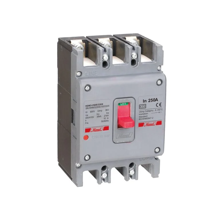
MCCB or MCB? How breaking capacity, the IEC 60898-1 and IEC 60947-2 standards, selectivity and temperature derating decide the right breaker for each board.
Read more
Soft starter or VFD for your pump? Compare starting current, running energy, harmonics and cost, with a decision matrix by pump duty, worked numbers and Singapore…
Read moreSend us your motor rating, voltage, application and quantity. We'll get back to you fast.